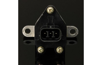
Introduction to the ELecdeer vehicle speed sensor, including sensor pins, parameters, and measurement methods.
1. Working principle
The vehicle speed sensor is a device used to detect the vehicle speed of an electronically controlled vehicle. The control computer uses this input signal to control the engine idle speed, the torque converter lock of the automatic transmission, the shifting of the automatic transmission, the opening and closing of the engine cooling fan, and cruise control. Prevent vehicle speed from being too high, limit engine fuel injection and other functions.
The output signal of the vehicle speed sensor can be a magnetoelectric AC signal, or a Hall digital signal or a photoelectric digital signal.
The vehicle speed sensor is usually installed in the drive axle or the transmission housing, and the signal line of the vehicle speed sensor is usually installed in a shielded jacket. Electronic communication is not interrupted, preventing poor drivability or other problems.
2. Related to the speed sensor
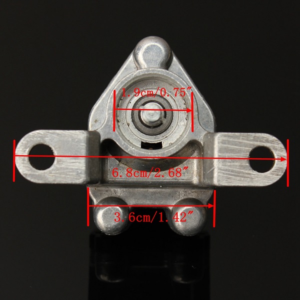
The power supply line of the vehicle speed sensor generally has 12v, 9v and 24v, and its wiring harness is also divided into three lines and four lines. Its installation location is generally on the gearbox.
The configuration of different cars will have different sources of speed. Here are a few situations to share with you:
First case:
Both the vehicle speed received by the ECU and the vehicle speed of the odometer are provided by the vehicle speed sensor on the gearbox, and are directly connected to the ECU and the instrument.
Generally, the power supply is provided by the meter, the ground wire is provided by the ECU, and the signals are respectively input to the meter and the ECU.
Second case:
The vehicle speed sensor is directly connected to the meter, and transmits the vehicle speed signal through the CAN line, VCU and ECU.
Both the vehicle speed received by the ECU and the vehicle speed of the odometer are provided by the vehicle speed sensor on the gearbox, and are directly connected to the ECU and the instrument.
The third case:
The vehicle speed displayed on the instrument is measured by the wheel speed sensor, calculated by the ABS, and sent to the instrument through the CAN line; the vehicle speed read by the diagnostic instrument is directly transmitted to the ECU by the vehicle speed sensor on the gearbox to determine the gear position and participate in the calculation of fuel injection Quantitative. In this case, two speeds will actually appear. If the two vehicle speeds are different, it may be that the wheel speed sensor or the vehicle speed sensor is abnormal.
3. Vehicle speed sensor measurement (EDC17CV44 as an example)
Put the ignition switch in the OFF position (if the last state of the ignition switch was ON, after setting it in the OFF position, you need to wait at least 60 seconds before performing subsequent operations)
Plug in the ECU harness connector
Plug in the dashboard harness connector
Put the ignition switch in the OFF position
Start and drive the vehicle
Measure the waveform of the vehicle speed signal with an oscilloscope through the jumper box
Note: The positive pole of the oscilloscope is connected to the ECU pin 22, and the negative pole is connected to the car ground.
Normal voltage value: 0V 10~14V 20HZ (20km/h)